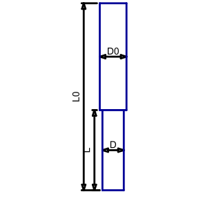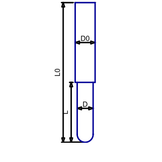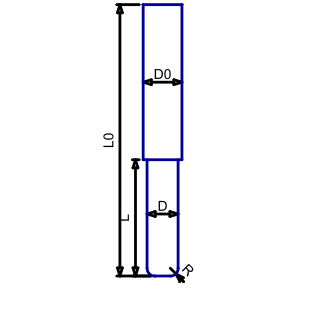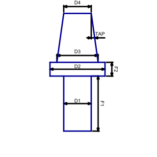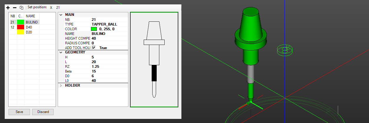
The interface is divided into three sections:
- Tool List: Displays the tool name, color, and station number where the tool is mounted. Use the ‘Add’, ‘Remove’, or ‘Copy’ commands to manage the tool list. Additionally, ‘Set Position’ buttons are available to quickly mount the selected tool in a station defined in the current NC file. Use ‘Set Position X’ to remove any assigned station number.
- Tool Settings: Allows configuration of all parameters for the tool selected in the tool list.
- Tool Geometry Representation: Shows a visual representation of the tool’s geometry.
Main
| Parameter | Description |
|---|---|
| Nb | The tool number or station number to be called in the NC file. |
| Type | Tool type. See the geometry section for details. The ‘Null’ tool displays a tool marker instead of actual tool geometry, while the ‘STL’ type allows loading an STL file to define the tool’s geometry. |
| Color | Tool color. |
| Name | Tool name. |
| Radius compensation | Specifies the tool radius compensation. |
| Height compensation | Specifies the tool height compensation. |
| Add tool holder | Adds a 3D representation of the tool holder when active. See the geometry section. |
