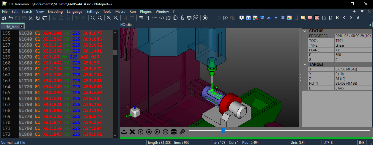
NCnetic includes all the essential tools to easily set up and simulate 4-axis NC files. This page covers the basic settings required to configure NCnetic for accurate simulations.
By convention, the addresses in the NC file are as follows:
- A: rotation around the X-axis
- B: rotation around the Y-axis
- C: rotation around the Z-axis
You can customize these by remapping the addresses in the options.
4 axis Rotary Tables
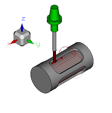
The most common type of 4-axis CNC machine has a part holder mounted on a rotary table to perform rotational machining, multi-side milling, or simply to change parts fixed on different sides of the table.
The origin of the Z-axis (Z=0) may coincide with the rotation axis (‘Rotary Z offset radius’=0, the default setting), or be on the surface of the part. In the latter case, the radius of the cylindrical part must be entered in ‘Rotary Z offset radius’.
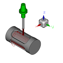
4 Axis Tool tilting
This configuration often corresponds to a choice of toolpath representation rather than an actual hardware feature (although such machines do exist). In this case, the rotation values represent a tilt of the tool rather than the rotation of the part. The advantage of this notation is that the XYZ values for the tool position remain unaffected by the rotations.
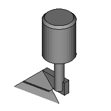
“Tangential” tools
The ‘XYZ_C_HEAD’ configuration of a 4-axis machine is used when the rotation of the tool around its own axis is critical. A common example is tangential knife or blade cutting, where the cutter must be oriented in the direction of tool travel to cut the material accurately.


